RS485 is a bus system for exchanging serial data over relatively long cables. In that sense it is similar to RS232, I2C, SPI, CAN and other standards.
Arduino does not natively support RS485. There are cheap breakout boards that contain a MAX485 chip that convert from the Arduino’s UART TTL voltage levels to the RS485 voltage levels.
The idea of a bus is that a message is put onto the bus and all participants read that message at the same time. Writing to the bus causes collisions if the bus already is written to by one of the other participants. That means only a single participant is allowed to write to the bus at any point.
As RS485 is a bus and hence a way to prevent collisions is needed. On scheme is to have a bus master that talks to slaves via id’s send in messages. Each slave checks if the message contains it’s address and only answers it the Id’s match. For the first test, such an elaborate scheme is not used.
Another way to use the bus is to have one participant send data and all other participants never write to the bus but only receive from the bus.
To test the RS485 transmission, the simple read-only case is used. One Arduino will write to the bus, another Arduino will only read from the bus. The writing Arduino will send an integer between 0 and 180 and the reading Arduino will control a servo and make the servo take a position between 0 and 180 degrees based on the integer that it receives from the RS485 bus. The idea is taken from https://create.arduino.cc/projecthub/maurizfa-13216008-arthur-jogy-13216037-agha-maretha-13216095/modbus-rs-485-using-arduino-c055b5
Lessons learned
Here are some mistake that I made and things I learned. To not let the reader make the same mistakes, here is a list of things to keep in mind before building the setup.
- When using a breadboard for insert jumper wires, do not forget to bridge the VCC and GND rows at the bottom and at the top of the breadboards together. Initially, the rows do not connect all the way through, they are separated in the middle. I made the mistake to route GND and VCC to the left end of the row and using GND and VCC on the right end of the row without ever bridging left and right side together with the effect that some of the components did not have any power at all.
- When the RS485 breakout boards are powered up, they light up a red LED. When data is transmitted the LED stays lit. The LED never starts to blink! The LED will not signal transmission, it is RED all the way. RED here is not the color of an error, it is the color of succesfull operation.
- The Ardunio’s serial pins are used to send data to the RS485 breakout boards. A jumper wire connects the Arduino’s TX and RX pins to the (D)river and (R)eceiver pins on the RS584 breakout board. Whereas a Arduino UNO has a single RX/TX pin pair, the Arduino Mega 2560 has four pairs RX0/TX0 through RX3/TX3. In the sketch, If you want to use the pair RX1/TX1 on the Mega, you have to call Serial1.begin(9600); Serial1.available() and Serial1.read() instead of merely calling Serial. For me it only worked with the RX1/TX1 pair on the Mega and calls to Serial1!
- A simple pair of wires to connect two RS485 breakout boards together worked for me. There is documentation that mentions to add a resistor between the two A and B wires. I did not add any resistance and the system still worked. The cable used is only about 30 cm long. Maybe the cable is too short to require any resistance, I do not know.
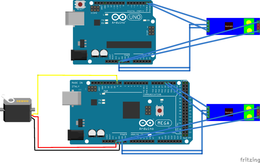
Connecting Components together
I am not a fritzing expert yet, so the image is rather wierd and I apologize. The DI and RO are connected to the serial pins on the arduinos. Also VCC and GND is connected. The Arduino Mega 2560 also drives the servo using pin 9 as a data line.
Although not visible in the fritzing, the two RS485 modules are connected via two simple wires referred to as A and B in RS485 terminology. There is no resistor used. The resistors on the RS485 modules have not been removed as they form the ends of the bus lines and have to be terminated.
On the sender side, DE and RE are both connected to 5V to enable the driver and disable the receiver.
On the receiver side, both DE and RE are connected to GND to disable the driver and enable the receiver.
Sketches
The sketch for the sender (Arduino UNO) is
int pos = 0;
void setup()
{
  Serial.begin(9600);
}
void loop()
{
  // sender
  // goes from 0 degrees to 180 degrees
  // in steps of 1 degree
  for (pos = 0; pos <= 180; pos += 1) {
     Serial.write(pos);
     delay(50);
  }
  // goes from 180 degrees to 0 degrees
  for (pos = 180; pos >= 0; pos -= 1) {
    Serial.write(pos);
    delay(50);
  }
}
The sketch for the receiver (Arduino Mega 2560) is:
include <Servo.h>
Servo myservo;
void setup()
{
  Serial.begin(9600);
  Serial1.begin(9600);
  myservo.attach(9);
}
void loop()
{
  // receiver
  if (Serial1.available()) {
    int angle = Serial1.read();
    if(angle<=180)
    {
      myservo.write(angle);
    }
  }
}