SMSC LAN9512 / SMSC LAN9514 dev board by matrixstorm / matrixprog

Stephan Bärwolf aka. Matrixstorm aka. matrixprog created a circuit board for the  SMSC LAN9512 / LAN9514 USB controller ethernet chip. This page describes my advances with his board.

About the LAN951X Chip

The company SMSC was aquired by Microchip and created the LAN9512 and LAN9514 chips. These chips are USB hub controllers and also contain an ethernet controller. They allow to convert USB transfers to ethernet packets. The LAN9512 supports 2 USB ports, the LAN9514 supports 4 USB Ports, the last digit determines the amount of supported USB ports.

The LAN951X is important because it is used in the early Raspberry Pi Models and the BeagleBone boards. When writing an operating system for those boards, it is required to have a working driver for the LAN951X controller.

An open source driver for the LAN951X exists in the linux operating system and also in the embedded Xinu codebase. A custom operating system can model those drivers.

About Matrixstorm’s Board

Matrixstorm’s Board is described on several forum entries and in one github repository.

https://www.mikrocontroller.net/topic/457051

https://www.mikrocontroller.net/topic/413047?goto=new#new

https://www.ebay.de/itm/LAN951X-Adapterboard-Basisplatine-inkl-Komponenten-OHNE-LAN951X/233193113581?_trkparms=aid%3D111001%26algo%3DREC.SEED%26ao%3D1%26asc%3D20170511121231%26meid%3D31fbe704dece42cf9703a6459ca5f905%26pid%3D100675%26rk%3D5%26rkt%3D15%26mehot%3Dnone%26sd%3D233832330319%26itm%3D233193113581%26pmt%3D0%26noa%3D1%26pg%3D2380057&_trksid=p2380057.c100675.m4236&_trkparms=pageci%3Adb26b22d-501a-11eb-9290-c2d29be0b34e%7Cparentrq%3Ad7aca2f71760a9c98cd4a5aefff12fc4%7Ciid%3A1

https://github.com/dumpsite/LAN95XX-board

The second link contains images of a carrier board that contains Ethernet Jacks to which the LAN951X board is attached.

Next Steps…

  • Prepare the reflow oven.
  • Assemble the board.
  • Add interfaces (USB plug and ethernet connector)
  • Attach the entire board to a windows PC via USB for testing.

Using the ASIX USB Ethernet controller with the Teensy 4.1

This blog post documents how a ASIX USB Ethernet adapter can be connected to a Teensy 4.1 board. As USB ethernet adapter, the widely supported (Linux drivers exist) adapter from Olimex is used. It contains the ASIX USB ethernet controller chip.

The Teensy board contains native ethernet support. This article is not about the native ethernet on the teensy but rather about the native USB host controller support that the teensy has. This article describes how to connect a ASIX USB Ethernet adapter to the USB controller on the teensy 4.1 to send ethernet packets to an IP address.

The FNET library contains an example called ASIXEthernet_Test.ino. This example can be executed on the Teensy 4.1 via the Arduino IDE.

The FNET example imports the ASIX driver for the Teensy which is contained in this repository. So first, install the FNET library and the TeensyASIXEthernet library via .zip or via the library manager into your Arduino IDE.

The teensy 4.1 comes in several offers. One option is to buy a Teensy that already has pin headers soldered in by a professional so you do not have to solder anything. If you have a teensy 4.1 that has no pins soldered to the USB contacts on the board, solder five pins in. This page contains pictures on where the USB cables are connected on the Teensy 4.1 and this shows you where to solder the USB pin header in. If you turn the Teensy 4.1 around, the bottom of the PCB contains the pin names on the bottom silk screen. USB On the Go added a fifth pin. This fifth pin is just connected to ground on the host side of a normal USB connection. For this example, only four of the five pins are required. The pins are 5V (red), D- (white), D+ (green) and ground (black).

As usual soldering makes better contact than just loosely sticking pin headers into the holes. The contact is only really established through the solder! If your setup does not work (No USB or ethernet connection), check your soldering again! For myself, it only worked after fixing my solder work once.

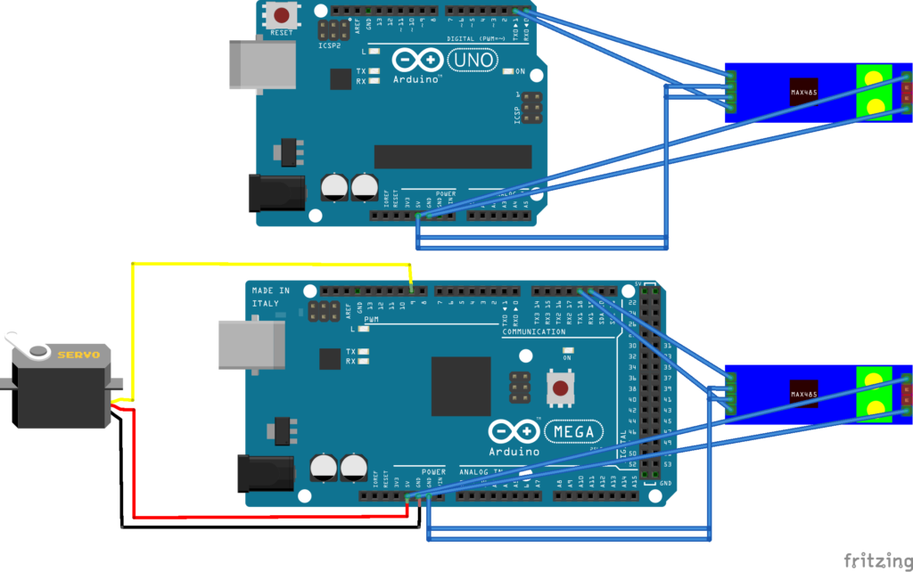
The next step is to connect the ASIX USB ethernet controller to the USB pins. For that, you can purchase USB adapter cables that have headers on one side and a USB port connector (MAKE SURE TO NOT ACCIDENTLY BUY A USB PLUG CABLE BUT A USB PORT CABLE!) on the other side. A depiction of such a cable is given here. Plug in the ASIX USB ethernet adapter in either directly or indirectly via a USB hub if you like. Connect a ethernet wire to the adapter and connect it to your home network that should contain a DHCP server so that the FNET stack can retrieve an IP address.

In the Arduino IDE open the FNET example sketch ASIXEthernet_Test.ino. Compile it and upload it to the teensy 4.1. Do not forget to change the target hardware to the Teensy 4.1 board in your Arduino IDE. If you target the wrong board, the headers used in the example sketch will not be found.

Unplug and reconnect the Teensy to your computer via USB to give it power. Open the serial monitor and wait. The example sketch will start the FNET stack in the background, this will take some time and there is no output whatsoever that tells you to wait. Once the stack is done, it will retrieve a IP address via DHCP and output something similar to this:

SetMACAddress: 00001001B3BD
netif Initialized
Initializing DHCP
DHCP initialization done!
IPAddress: 0.0.0.0
SubnetMask: 0.0.0.0
Gateway: 0.0.0.0
DHCPServer: 0.0.0.0
State: 2
IPAddress: 192.168.0.10
SubnetMask: 255.255.255.0
Gateway: 192.168.0.1
DHCPServer: 192.168.0.1
State: 5

The LEDs inside the USB Ethernet adapter casing should begin to light up and flicker.

Once you see this output, it is time to instruct the Teensy to send ethernet packets. In order to do that, the example sketch uses the FNET benchmark code. You can start the benchmark by sending a command to the Teensy via the Serial Monitor’s send feature. The benchmark has several options so here is one example command:

benchtx -a 192.168.0.234 udp -m 1272

First of all: You have to send a space after the last character. So before sending this command, make sure there is a trailing space! The parser of the FNET benchmark code is very peculiar about the input it wants to accept! If there is no space, the command is rejected!

The benchmark tools command line is:

benchtx -a <remote_ip> [tcp|udp] [-m <message size>] [-mn <number of messages>]

For me, the last optional flag -mn never was accepted by the parser hence the example command above does not specify a message number. The default message number of 10000 messages is used. The message size default value is 1272. The example command uses UDP for no specific reason. The remote IP is the IP of the device in your local network that should receive the ethernet packets.

The FNET benchmark code will blast out 10000 packets as fast as it can not careing about packet loss or anything. It will not wait in between packets and it will output a single line of statistics about the burst send after it is done.

Megabytes: 0.587664  Seconds: 0.1250  KBits/Sec: 37610.4960

In a running instance of wireshark on the remote machine, you can see some of the 10000 packets arrive. If you have a means to count the incoming packets, you could check how many of the UDP packets actually made it and you could compute the success rate of the burst transfer.

Receiving Ethernet Packets

For receiving ethernet packets over the ASIX USB Ethernet Adapter, the code in the ASIX example has to be modified! The code contains a variable called MacAddress.

uint8_t MacAddress[6] = {0x00,0x50,0xB6,0xBE,0x8B,0xB4};

The MacAddress variable contains the six byte long MacAddress that is used to participate in an Ethernet Network. The MacAddress uniquely identifies the Ethernet Adapter in an Ethernet Network just as the IP-Address identifies a node in an IP Network.

In contrast to an IP Address, which has local scope (per subnet and local LAN) and which can be dynamically leased by a DHCP server and hence is not necessarily unique globally, a MacAddress is a globally unique identifier.

Every Ethernet capable device gets a unique MacAddress assigned by the vendor or manufacturer of the device. The Olimex Adapter has a unique MacAddress. This MacAddress differs from the MacAddress that is part of the ASIX example code!

Using the MacAddress from the ASIX example without change causes the example code to send Ethernet frames into the network that contain this incorrect MacAddress. Communication partners will then answer using that incorrect MacAddress. The Olimex Adapter will see the ethernet frames and it will compare it’s own MacAddress to the one contained in the frames. It will decide that those frames are directed at another participant because the MacAddresses do not match! It will then discard those frames and your code will not ever receive even a single frame!

To solve the problem, determine the MacAddress of your particular Olimex adapter and update the example code with that MacAddress. One way to determine the MacAddress is to plug the adapter into a windows host and on the command line, execute the ipconfig /all command with lists the MacAddress.

One tip for safety, keep you MacAddresses off the Internet, that means do not check in your MacAddress into a git repository, just as you do not check in any passwords into git repositories. If someone really wants to hurt you, commiting your MacAddress to git connects the MacAddress to your person or git account which opens up a way for attackers.

Sending and Receiving Speeds

For sending out Ethernet frames, your code can send as fast as possible because the performance of the Teensy 4.1 CPU and the speed of the USB controller and ethernet PHY naturally limit the amount of packets send. Packets will most likely not be lost during the send operation. The chips will process the packets when they get to it.

On the receiving side, I encountered problems. Sending from a MAC Book Pro which has a fast CPU and a really high quality ethernet chip can easily overpower the Teensy 4.1 with the Olimex Adapter attached. Packets where dropped and not received. I assume that because USB is a polled bus that if your system does not poll fast enough, ethernet frames are just dropped.

Another test showed that when connecting the Olimex Adapter to a powerfull business laptop running windows, the same effect can be observed. Even on capable hardware, the Olimex Adapter drops frames.

To test the situation, I used the code from https://www.vankuik.nl/2012-02-09_Writing_ethernet_packets_on_OS_X_and_BSD

Here, a byte array of data is sent to a MacAddress of your choice, which is the Olimex adapter’s MacAddress in this test. The byte array is larger that the maximum allowed length of a single ethernet frame hence the code constructs several frames and sends them out. In this test, four frames are send. The variable in the test is the amount of time the  code sleeps (usleep(uint microseconds)) between each of the four ethernet frames.

Using wireshark, on the sender’s side, it is checked how many frames are really sent by the test program. Using wireshark on the receiver’s side, it is checked how many packets are actually received.

The breaking point for the Olimex adapter seems to be a sleep time of 1 ms. Sleeping more than 1 ms causes the Windows Machine to receive every single frame correctly.

Going down to 1 ms and lower, causes the Windows machine to not receive all packets. Because this effect shows on the windows machine and on the Teensy, I have to assume that it is a problem with the Olimex USB adapter and not in the example code or in windows. It might also be because USB is a polled bus, but the Business laptop should be able to poll the USB Adapter faster than the Teensy but still the same effect is noticeable.

With a lossless protocol such as TCP, lost packets will be retransmitted and the transfer should be possible even if the sender overwhelmes the receiver. With a lossy ethernet or UDP connection, this is a real problem!

Conclusion

The amazing thing about all this is that you have the code for an open source TCP/IP stack (FNET) and a working ASIX driver (https://github.com/vjmuzik/TeensyASIXEthernet) that works over USB.

For learning about the USB protocol, I personally feel that this setup is a very motivating one because it allows you to learn about USB, TCP/IP and the low-level driver development in one go. This might be too much at once and become overwhelming pretty quickly but I think being overwhelmed is better than loosing interest because of a lack of exiting experiments.

Another big plus is that the USB connection to the ethernet adapter allows you to port the ASIX driver to any embedded system that has a USB host controller and that you want to connect to ethernet. This will work even if the embedded device has no native ethernet support or even if it has native ethernet support but there is no open source driver for the ethernet controller chip or if you do not understand the open source driver yet.

Anyways, I hope you took something away from reading this article. Thank you for your interest in my page.


Using a SNES Controller with an Arduino on a PC

Inspired by this github repository https://github.com/burks10/Arduino-SNES-Controller and the accompanying YouTube video https://www.youtube.com/watch?v=93oCS9nF_y0, I want to write down the steps I followed to get a SNES controller working on a PC without bying any SNES adapters or permanently and irreversibly modifying the controller.

The idea is that an Arduino is used to adapt the SNES controller to a USB HID Joystick device that the PC can use to control an emulator. For that the Arduino’s USB connector chip MEGA16u2 that takes care of the USB protocol on the Arduino is reprogrammed by flashing custom firmware to it. The solution also is able to flash back the original Arduino USB firmware, so you will not permanently alter your Arduino.

The USB firmware is contributed by the UnoJoy project which has it’s repository under https://github.com/AlanChatham/UnoJoy. UnoJoy supports the PS3 controller out of the box but not the SNES controller. burks10 added a sketch that is able to interpret the SNES commands and insert them into the data structures that the UnoJoy project mandates.

The software architecture is as follows. The USB protocol mandates that the USB controller inside your PC polls USB HID devices for input state. That means that the MEGA16u2 chip on the Arduino is constantly polled for input data. The custom UnoJoy firmware that is flashed to the MEGA16u2 will read a dataForController_t data structure from the sketch that runs on the Arduino. It will return this information back to the USB controller. The sketch on the Arduino will poll the SNES controller and it will interpret the signals as button or dpad presses. It will fill in the dataForController_t with the SNES controller’s button state. This is how a button press makes it from the SNES controller through the MEGA16u2 chip, through USB, through the PC’s USB controller to the emulator.

When the newly flashed Arduino is plugged in into the PC, it will register with the operating system as a HID Joystick. Selecting this HID Joystick in your emulator allows you to read input from this device.

Here are the steps in detailed order:

Hint / Important

Turn off USB Helper
Turn off all tools that might interfere with USB such as USB Overdrive.

Wire Up the SNES controller to the arduino.

Locking at the controller plug, there is a rounded corner and a flat corner.
Putting the flat corner on the left and the rounded corner on the right, the pins are numerate 1 through 7:

| 1 2 3 4 | 5 6 7 )

Connect Pin 1 on the controller to 5V on the Arduino, that means:

Controller Pin 1 <-> Arduino 5V
Controller Pin 2 <-> Arduino Pin 6
Controller Pin 3 <-> Arduino Pin 7
Controller Pin 4 <-> Arduino Pin 12
Controller Pin 7 <-> Arduino GND

Upload the correct sketch to the Arduino

git clone https://github.com/burks10/Arduino-SNES-Controller.git
Open Arduino IDE on the file snes/snes.ino
As a board, select the ardunio uno.
Validate and upload the sketch.

Install the dfu-programmer

see https://www.arduino.cc/en/Hacking/DFUProgramming8U2

sudo port install dfu-programmer

Install libusb and libusb-compat

Turn on DFU mode

Short the 2 pins closest to the USB port to enter DFU mode

Prepare the flashing of new firmware for the Ardunio USB controller chip

git clone https://github.com/AlanChatham/UnoJoy.git
cd UnoJoy/UnoJoy

Edit the file TurnIntoAJoystick.command file

Replace all occurences of ./dfu-programmer by dfu-programmer

Make it executable and run the command file:

chmod a+x TurnIntoAJoystick.command
./TurnIntoAJoystick.command

Connect the Ardunio to the PC

Unplug the arduino and plug it back in

Check if MacOS has detected a controller

MacIcon in the top left > About this Mac > Overview > System Report … > USB > check if there is an entry alled ‘UnoJoy Joystick’

Reverting the process (Getting back the normal Arduino Behaviour)

If you want your arduino back, enter DFU mode again.
While the arduino is plugged in to USB, short the pins shortest to the USB port.

Modify the file TurnIntoAnArduino.command and replace all occurences of ./dfu-programmer by dfu-programmer

Make it executable and run the command file:

chmod a+x TurnIntoAnArduino.command
./TurnIntoAnArduino.command


SainSmart USB Host shield for Arduino

What is this article all about?

This article explains how to run one of the example applications on the SainSmart USB Host shield on a Arduino Mega.

Another good article is https://hardwarefun.com/tutorials/using-usb-host-shield-with-arduino

The steps to get an example running are

1. Plug in the shield to the Arduino Mega 2560
2. Git clone the Library
3. Add the library to the Arduino IDE, then restart the IDE.
4. Open an example sketch, compile and upload the sketch.
5. Plugin a keyboard, restart the Arduino, inspect the example’s output via the Serial Monitor

Detailed Explanation

The SainSmart USB Host shield contains a MAX3421E chip which allows the Arduino to act as a USB host into which you can plug in USB client devices. The shield can be plugged in to a Arduino Mega 2560. I tested it without modifying the hardware and my Arduino Mega 2560 and the SainSmart USB Host shield still work.

On the software side, the github repository https://github.com/felis/USB_Host_Shield_2.0 conains the library including examples for the SainSmart USB host shield. To run an example, it is necessary to install the library into your Arduino IDE. First use git to checkout the library.

git clone https://github.com/felis/USB_Host_Shield_2.0.git

Open the Arduino IDE and select Sketch > Include Library > Add . Zip Library. A file/folder selector dialog opens. Point the dialog to the folder into which the repository got cloned and finish the import. Restart the Arduino IDE.

After starting the Arduino IDE, select File > Examples > USB Host Shield Library 2.0 > HID > USBHIDBootKbd. Plug a Keyboard into the USB shield, upload the sketch. Open a serial monitor from within the Arduino IDE: Tools > Serial Monitor. Reset the Arduino Mega 2560.

The serial monitor should now output some text whenever you hit a key on the keyboard.

Gotchas

If you get the error: ‘Keyboard’ not found. Does your sketch include the line ‘#include <Keyboard.h>’? you have accidently opened up an example for a board that supports USB natively. Those examples are contained under File > Examples > 09.USB. The examples under 09.USB are not the examples that work with the SainSmart USB Host shield! The working examples are located under File > Examples > USB Host Shield Library 2.0.

RS485 Communication between two Arduinos

RS485 is a bus system for exchanging serial data over relatively long cables. In that sense it is similar to RS232, I2C, SPI, CAN and other standards.

Arduino does not natively support RS485. There are cheap breakout boards that contain a MAX485 chip that convert from the Arduino’s UART TTL voltage levels to the RS485 voltage levels.

The idea of a bus is that a message is put onto the bus and all participants read that message at the same time. Writing to the bus causes collisions if the bus already is written to by one of the other participants. That means only a single participant is allowed to write to the bus at any point.

As RS485 is a bus and hence a way to prevent collisions is needed. On scheme is to have a bus master that talks to slaves via id’s send in messages. Each slave checks if the message contains it’s address and only answers it the Id’s match. For the first test, such an elaborate scheme is not used.

Another way to use the bus is to have one participant send data and all other participants never write to the bus but only receive from the bus.

To test the RS485 transmission, the simple read-only case is used. One Arduino will write to the bus, another Arduino will only read from the bus. The writing Arduino will send an integer between 0 and 180 and the reading Arduino will control a servo and make the servo take a position between 0 and 180 degrees based on the integer that it receives from the RS485 bus. The idea is taken from https://create.arduino.cc/projecthub/maurizfa-13216008-arthur-jogy-13216037-agha-maretha-13216095/modbus-rs-485-using-arduino-c055b5

Lessons learned

Here are some mistake that I made and things I learned. To not let the reader make the same mistakes, here is a list of things to keep in mind before building the setup.

  • When using a breadboard for insert jumper wires, do not forget to bridge the VCC and GND rows at the bottom and at the top of the breadboards together. Initially, the rows do not connect all the way through, they are separated in the middle. I made the mistake to route GND and VCC to the left end of the row and using GND and VCC on the right end of the row without ever bridging left and right side together with the effect that some of the components did not have any power at all.
  • When the RS485 breakout boards are powered up, they light up a red LED. When data is transmitted the LED stays lit. The LED never starts to blink! The LED will not signal transmission, it is RED all the way. RED here is not the color of an error, it is the color of succesfull operation.
  • The Ardunio’s serial pins are used to send data to the RS485 breakout boards. A jumper wire connects the Arduino’s TX and RX pins to the (D)river and (R)eceiver pins on the RS584 breakout board. Whereas a Arduino UNO has a single RX/TX pin pair, the Arduino Mega 2560 has four pairs RX0/TX0 through RX3/TX3. In the sketch, If you want to use the pair RX1/TX1 on the Mega, you have to call Serial1.begin(9600); Serial1.available() and Serial1.read() instead of merely calling Serial. For me it only worked with the RX1/TX1 pair on the Mega and calls to Serial1!
  • A simple pair of wires to connect two RS485 breakout boards together worked for me. There is documentation that mentions to add a resistor between the two A and B wires. I did not add any resistance and the system still worked. The cable used is only about 30 cm long. Maybe the cable is too short to require any resistance, I do not know.

Connecting Components together

I am not a fritzing expert yet, so the image is rather wierd and I apologize. The DI and RO are connected to the serial pins on the arduinos. Also VCC and GND is connected. The Arduino Mega 2560 also drives the servo using pin 9 as a data line. 

Although not visible in the fritzing, the two RS485 modules are connected via two simple wires referred to as A and B in RS485 terminology. There is no resistor used. The resistors on the RS485 modules have not been removed as they form the ends of the bus lines and have to be terminated.

On the sender side, DE and RE are both connected to 5V to enable the driver and disable the receiver.

On the receiver side, both DE and RE are connected to GND to disable the driver and enable the receiver.

Sketches

The sketch for the sender (Arduino UNO) is

int pos = 0;
void setup()
{
Serial.begin(9600);
}
void loop()
{
// sender
// goes from 0 degrees to 180 degrees
// in steps of 1 degree
for (pos = 0; pos <= 180; pos += 1) {
Serial.write(pos);
delay(50);
}
// goes from 180 degrees to 0 degrees
for (pos = 180; pos >= 0; pos -= 1) {
Serial.write(pos);
delay(50);
}
}

The sketch for the receiver (Arduino Mega 2560) is:

include <Servo.h>
Servo myservo;
void setup()
{
Serial.begin(9600);
Serial1.begin(9600);
myservo.attach(9);
}
void loop()
{
// receiver
if (Serial1.available()) {
int angle = Serial1.read();
if(angle<=180)
{
myservo.write(angle);
}
}
}

Servo on Arduino Mega 2560

This post describes how to connect a 5V Servo to an Arduino Mega 2560.

The Servo needs GND, 5V and a data line. The Arduino Mega 2560, once powered via a USB Cable, is able to provide these three signals to the servo.

You can use three male to male jumper wires to connect the servo to the Arduino Mega 2560. Connect the data line to pin 9 on the Arduino Mega 2560 so it directly matches the Sketch outlined below.

As a sketch, the example sketch found under File > Examples > Servo > Sweep worked perfectly. It turns the servo to either ends of it’s 180 degree range.

/* Sweep
by BARRAGAN http://barraganstudio.com
This example code is in the public domain.
modified 8 Nov 2013
by Scott Fitzgerald
http://www.arduino.cc/en/Tutorial/Sweep
*/
include <Servo.h>
Servo myservo; // create servo object to control a servo
// twelve servo objects can be created on most boards
int pos = 0; // variable to store the servo position
void setup() {
myservo.attach(9); // attaches the servo on pin 9 to the servo object
}
void loop() {
for (pos = 0; pos <= 180; pos += 1) { // goes from 0 degrees to 180 degrees // in steps of 1 degree myservo.write(pos); // tell servo to go to position in variable 'pos' delay(15); // waits 15ms for the servo to reach the position } for (pos = 180; pos >= 0; pos -= 1) { // goes from 180 degrees to 0 degrees
myservo.write(pos); // tell servo to go to position in variable 'pos'
delay(15); // waits 15ms for the servo to reach the position
}
}

Arduino and Ethernet Module

Using the Deek-Robot NANO Ethernet Shield V1.0 and the UIPEthernet library, it is possible to add Ethernet capabilities to an Arduino microcontroller. The process is outlined in this excellent article: https://www.tweaking4all.com/hardware/arduino/arduino-enc28j60-ethernet/

A webpage served by the Arduino microcontroller gives you the opportunity to provide a nice, modern user interface to the users of your arduino project from any connected device be it a mobile device such as a smartphone or a desktop PC. You can connect hardware to the arduino which you can then control based on button clicks to the web page you serve to the local network via the Arduino web page. Besides webpages, the Arduino can now provide a REST-API which you could consume from a Angular-Application. REST-APIs allow you to seamlessly integrate the Arduino-Project into existing web applications.

This post documents the individual steps I took to follow the article on tweaking4all.

I used an Arduino UNO, the Deek-Robot NANO Ethernet Shield V1.0 (contains a ENC28J60 chip), Arduino IDE 1.8.9 and the UIPEthernet Sketch from the article on tweaking4all.

First, you have to install the UIPEthernet library into your Arduino IDE. The UIPEthernet library is needed, because the ENC28J60 does not work with the standard Ethernet libraries that ship with the Arduino IDE. The Arduino IDE allows the installation of libraries from Zip-Files. The Zip-File for the UIPEthernet library is conveniently retrieved by downloading the master branch of the Github Repository as a zip file: https://github.com/UIPEthernet/UIPEthernet > Clone or Download > Download zip. Once the zip file is contained on your harddrive, you can import it via the Arduino IDE’s installation feature: In the Arduino IDE, navigate to Sketch > Include Library > Add .ZIP Library. At the top of the drop down list, select the option to “Add .ZIP Library”. If the installation worked, the Arduino IDE will output: Library added to your libraries. Check “include library” menu.

Secondly, wire up the Deek-Robot board to your arduino. The page tweaking4all has a nice image on which pins have to be connected to which pins on the Arduino UNO. You need ground and 5V. My board did not die on 5V so I figure it is true that the Deek-Robot board contains a voltage converter that changes 5V to 3.3V. You have to connect the pins D10, D11, D12, D13 on the Deek-Robot board to the pins 10, 11, 12, 13 on the Arduino board in the same order (D10 is connected to 10, D11 is connected to 11, …). Also, connect a Ethernet cable between the Deek-Robot board and your home network.

Thirdly, you have to set up your router in your home network. Normally, every mac address that connects to the router gets a dynamic IP-Address assigned via DHCP which is a protocol that temporarily leases IP-Addresses to devices. Because DHCP’s use case is to connect a device that only consumes services on the network, the IP-Address is dynamic and not known before the device is connected. Without retrieving the devices IP from the device itself or from your router, you have no way to connect to the device to consume its services. The Arduino sketch contains a mac Address and a fixed IP-Address because we want to connect to the Arduino via a known IP-Address. To prevent DHCP from assigning a dynamic address, a rule is added to the router that assigns a fixed IP-Address to the mac-Address from the sketch. Weather your router is able to add rules and how to add a rule, I can not tell you because I do not know all the routers. Consult your router’s manual to add a rule. Add such a rule, then update the Sketch to contain the mac- and the IP-Address specified in the rule.

As a fourth step, you can now paste the sketch for the UIPEthernet library with correct mac and IP-Address set from tweaking4all into your Arduino IDE, connect your Arduino and Upload the sketch.

Once the sketch has been succesfully uploaded, open the IP address and port 80 in a web browser on a machine that is connected to your home network. Before connecting via the browser, you can open a serial terminal to the arduino. The Arduino will output information about a established connection into the serial terminal. Your browser will execute a GET-Request towards the Arduino Server and it will retrieve the small HelloWorld HTML-page that the sketch predefines. After serving the page, the connection is terminated by the Arduino server.

That is it! Basically if you know how to connect the board, install the library, set up a DHCP rule and after reading the article on tweaking4all, you can make your Arduino available in your home network. A downside of this approach is that the Deek-Robot board uses pins 10, 11, 12, 13 on your arduino. They are blocked for other boards. The next steps would be to figure out how to serve more resources than just the hello world webpage! How would you serve several pages connected to each other via hyperlinks for example? How do you server static resources such as CSS, JS and image files? Nevertheless, connecting the Arduino to the Ethernet network, enables your Arduino projects from your smartphone! A lot is possible. Have fun with your projects and thank you for reading this article.